

MCAD/Mathcad
DIGITEK is always doing our best to think ahead for customers
and create new value for your business.
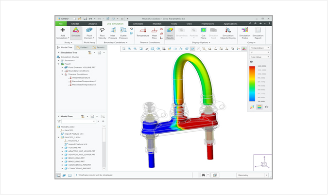
MCAD – Creo Simulation Live & ANSYS Simulation extension
Effective tool for simulation-based drawing. Now users can simulate real-time structure, thermal vibration, and fluid flow on Creo Simulation Live. As one of the methods of daily workflow, it provides more guidelines such as parameters, print/graphics, and overheat information.
Creo ANSYS Simulation not just provides guideline direction, but also provides various functionality set for validating fidelity of drawing. When using Creo ANSYS Simulation, users can easily analyze structure, modal and thermal data by directly accessing ANSYS solver which is proven as a highly qualified product on Creo.
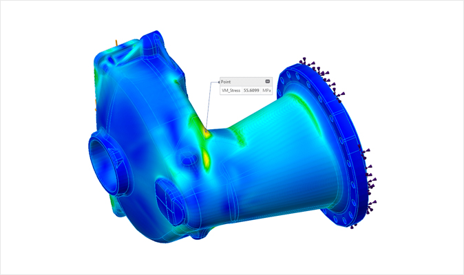
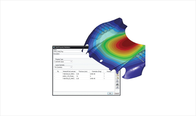
MCAD – Creo Simulate
Creo Simulate has the capacity to evaluate the structural and thermal dynamic performance of products based on the digital models so designers have no need to consume their time and cost to actually make a prototype. When designers need to identify the properties of a product, they can save time, cost, and efforts and improve the quality of product instead.
1Interpretation
- Linear static structural analysis
- Compact static structural analysis
- Deflection point
- Modal structural analysis
- Linear buckling structural analysis
- Thermal interpretation of linear stabilization status
- FEM mode: NASTRAN Solver used
- FEM mode: ANSYS Solver used
- Fatigue (optional module)
2Convergence
- P-type limited factor methodology
- Adaptation of single pass
- Adaptation of multilateral pass
- User control of convergence standards
- Automated adjustment of sizes of surrounding factors and special processing
3Structural Boundary Conditions
- Figure-defined boundary condition
- Forced transition and rotation
- Asymmetry and repeated asymmetry restraint condition
- Plane, pin, and ball restraint condition
- Force and moment load
- Pressure load
- Bearing load
- Gravity load
- Central load defined by a structure’s angular velocity or angular acceleration
- Inertia load
- Load from Creo mechanism analysis
- Temperature load
4Thermal Boundary Condition
- Figure-defined boundary condition
- Pre-defined temperature
- Convection condition
- Regular asymmetry restraint condition
- Thermal load
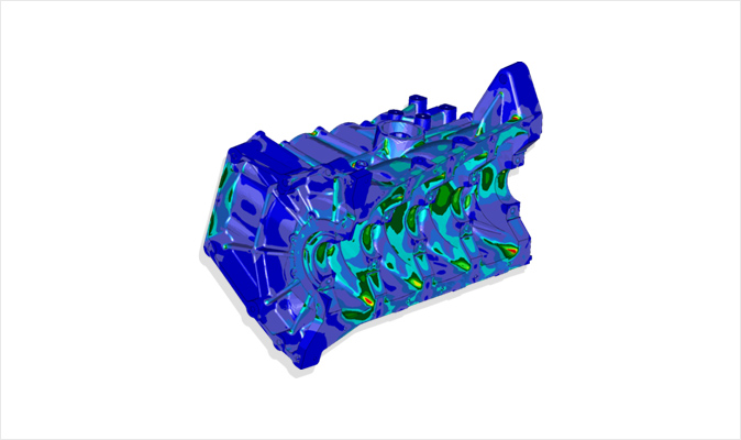
MCAD – Creo Advanced Simulate
Creo Advanced Simulate expands the feature to learn how much Creo Simulate and advanced/nonlinear effect can affect product design.
PTC Creo Simulate and PTC Creo Advanced Simulation Extension are productivity tools that standardize the same user interface, workflow, and PTC Creo products. The combination of PTC Creo Simulate and PTC Creo Advanced Simulation Extension can be used as an independent applied program or expanded to PTC Creo Parametric.
1Interpretation
- Nonlinear static structural analysis
- Dynamic structural analysis
- Preliminary stress structure static analysis
- Preliminary stress structure modal analysis
- Nonlinear stabilization status thermal analysis
- Excess thermal analysis
2Convergence
- Variable nonlinear repetition
- Excess adaptive solution
3Structural Boundary Conditions
- Bolt preliminary load
- Fundamental study for dynamic analysis
- Frequency Dependence of Load Sets for Frequency Response
- Time Dependence of Load Sets for Time Response
- Power Spectral Densities for Random Response
4Thermal Boundary Condition
- Excess thermal load
- Movable thermal load
- Excess convection condition
- Radiology condition
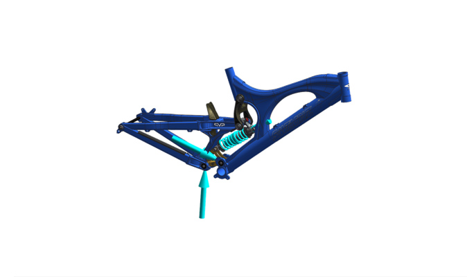
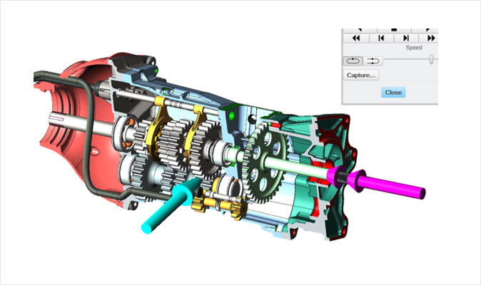
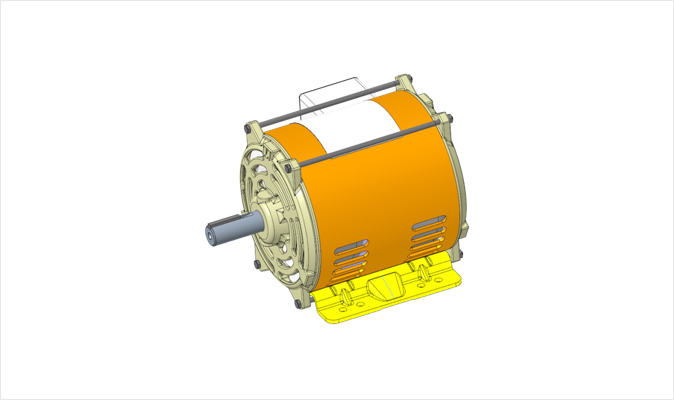
MCAD – Creo Mechanism Dynamics Option
Dynamics analysis using powerful prototype solutions
With PTC Creo Mechanism Dynamics Option (MDO), designers can virtually simulate the forces that actually work without wasting much cost to make the actual prototype and analyze a product’s response to the forces. Also, the product’s motion can be simulated in the early stage of design, so they can improve the quality of product and save time and cost.
With PTC Creo MDO, designers can instantly identify how their designs would respond to gravity, friction, and other dynamics right on their computers. This process of analysis can be executed without actually making a prototype, so they can test and correct any problems in the early stage for much less cost. When they actually build a prototype later in the process, its quality would be much higher as it has already been through a series of strict tests on the virtual platform. Also, they can save cost as they do not need as many prototypes as they did before and produce quality products 'without the trials and errors' to expedite the product release period.
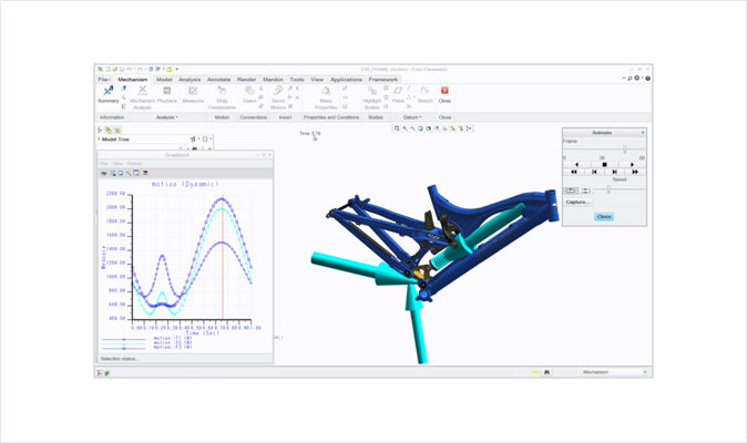
1Features & Specifications
- Identification of actual motions
- Easy to share the results through intuitive graphs
- Improves flexibility to identify the complexity of real life through advanced motion analysis
- Integration of design and simulation
2Benefits
- Uses perfectly integrated design and analytical tools to save time, efforts, and cost wasted by data conversion and related errors
- Creates virtual prototypes for desktop testing to save the cost of development
- As results can be acquired instantly through desktop testing, changes are reflected on products earlier and faster
- Shortens the development period to release quality products faster than others
- Predicts product lifespan more accurately to reduce the cost of warranty
- Uses specific animated assembly production guidelines to prevent manufacture errors that consume much cost
- Designers can evaluate more design ideas by saving time with virtual tests to produce more innovative products
- Easy-to-use intuitive user interface
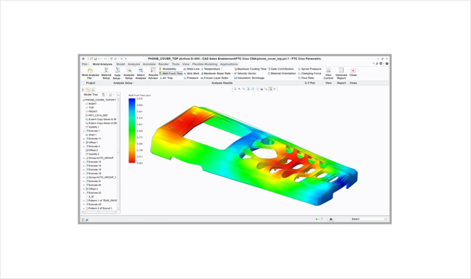
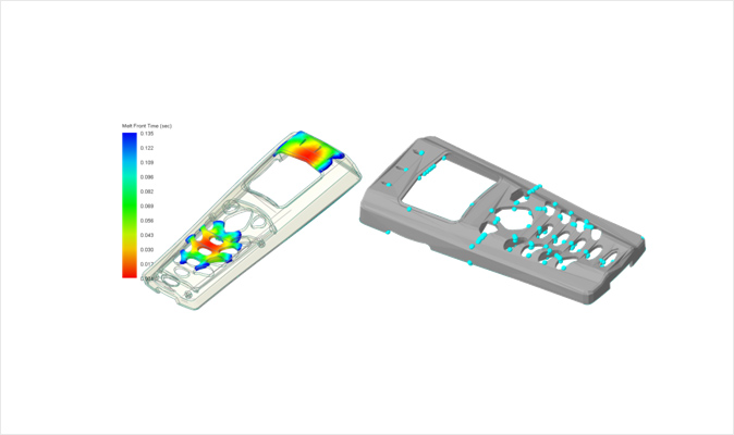
MCAD – Creo Mold Analysis Extension
Fast and accurate simulation for extrusion of plastic parts within PTC Creo Parametric™
With PTC Creo Mold Analysis Extension, you can simulate the extrusion of plastic parts fast and accurately within PTC Creo Parametric™. This tool allows the designer to identify the potential problems of products and optimize the design to improve the feasibility of manufacture.
With the features of PTC Creo Mold Analysis Extension, analysts and designers can acquire in-depth insights through the flow of plastic. This powerful tool analyzes the extrusion molding for design verification and optimization within PTC Creo Parametric to reduce the cost of mold redesign and design changes.
1Features & Specifications
- Process-centered intuitive user interface embedded in PTC Creo Parametric
- Animation feature on plastic extrusion process
- Inclusive database on general plastic materials
- Automatically applies the processing conditions optimized for the selected plastic materials
- Identifies the best position for insertion gate
- Appropriate solutions for potential problems such as insufficient charge, air trap, and welding line
- The true 3D solid solver providing more accurate results than the 2.5D technology
- Broad analysis
2Benefits
- Potential identification of problems related to extrusion charge, such as short shot, air trap, and welding line
- Improves quality and shortens the production and rework period
- Identifies the best place for extrusion to reduce cycle type
- Easy to use without extensive knowledge of plastic analysis
- Features embedded in Creo Parametric
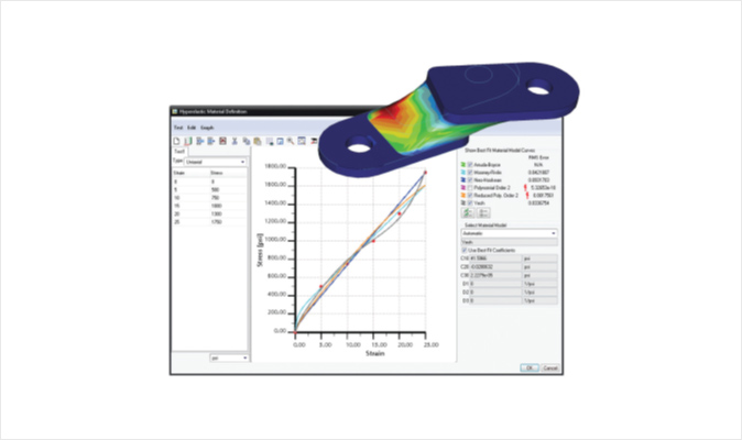
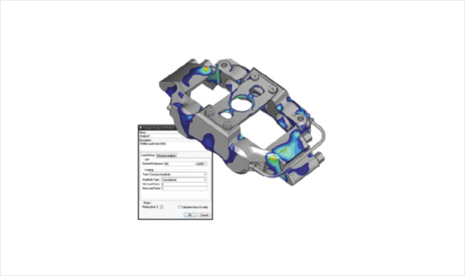
MCAD – Creo Fatigue Advisor Extension
Improves productivity of design through durability test of product design
PTC Creo Fatigue Advisor Extension expands the features applied to the evaluation of durability of Creo Simulate and product design. PTC Creo Fatigue Advisor Extension allows designers to predict the lifespan of materials and structures until fatigue failure by repeated load and survey the factors of design change that can affect the durability of products.
PTC Creo Simulate and Creo Fatigue Advisor Extension are the productivity tools that standardize the user interface, workflow, and PTC Creo products. The combination of PTC Creo Simulate and Creo Fatigue Advisor Extension can be used as an independent applied program or expanded to PTC Creo Parametric.
3D Solid Modeling
- Focus on Crack Initiation
- Strain – Life Analysis (EN)
- Effective for low and high cycle fatigue regions
- Consideration of plasticity
- Mean Stress correction
- Surface treatment and Finish correction
- Bi-axiality correction
Material Library
Load History
- Constant Amplitude
- Variable Amplitude
Results
- Number of cycles to failure (Life)
- Factor of Safety
- Confidence of Life based on specified desired number of cycles
- Results display on model
- Results recorded as Measures
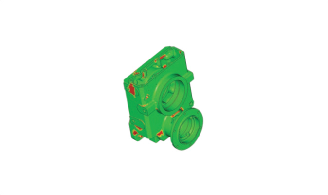
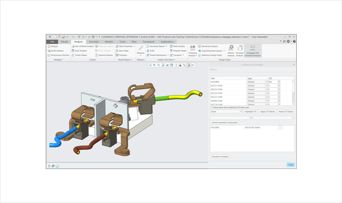
MCAD – Creo Clearance and Creepage Extension
Automated analysis of clearance and creepage
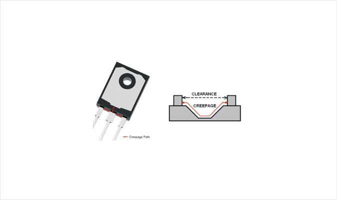
Safety of electrical appliances is essential for today’s competitive market. More products in the automotive, aviation and defense, electronics, and high-tech industries are adopting the mechatronics into their designs. Even the smallest errors in the design of electrical devices can lead to damaged circuits, overheating, and even fire and/or explosion.
Manufacturers are required to release products in the market faster than ever before and minimize the risk factors of product failure or damage for cost-efficiency.
Creo Clearance and Creepage Extension can secure the stability of products and optimize the detailed design process of electrical appliances.
1Features & Specifications
- Easy-to-use and automated clearance and creepage analysis
- Model setup
- Flexible analysis
2Benefits
- Automated analysis of direct electrical clearance and creepage of the digital model
- Clear identification of product safety issues
- Optimization of design for the safety of electrical devices to improve the quality of design
- Saves time and reduces the cost of prototypes
- Reduces rework and disposal of production
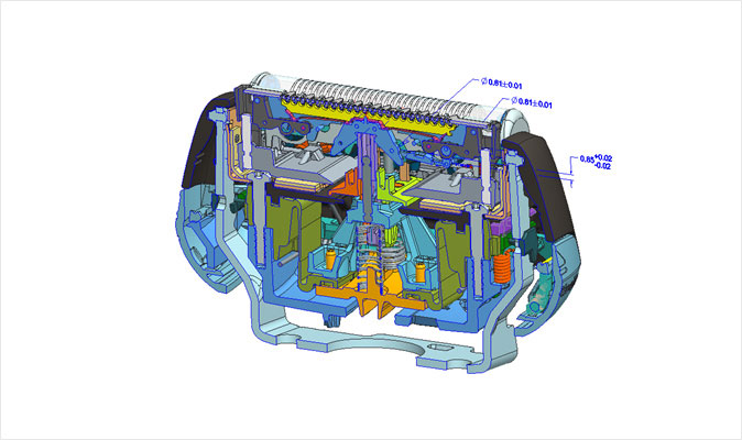
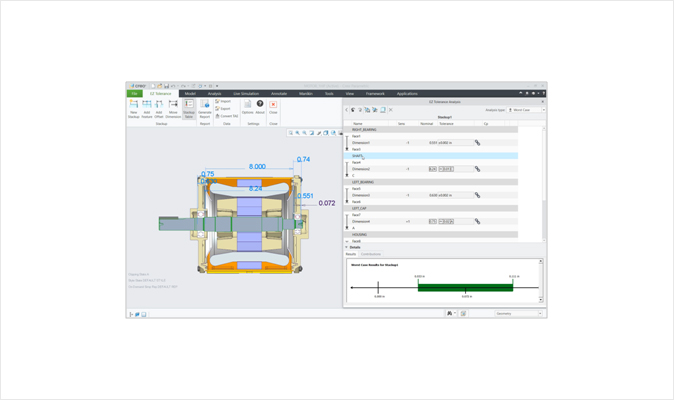
MCAD – Creo Tolerance Analysis Extension
Geometric tolerance and fluctuation analysis
In order to supply quality products to the market faster, designers must understand the impact of tolerance and fluctuations in manufacture in relation to product design. Design engineers can use PTC Creo TAE (Tolerance Analysis Extension) built on CETOL Technology for powerful analysis of tolerance on the design platform. They can easily analyze, visualize, and comprehend the geometric tolerance and fluctuation in dimensions that affect the design.
Designers need the highest level of solution in the market in order to satisfy the meticulous needs of the competitive global market today. In order to comprehend the related impact and produce a powerful design to prevent the failure of downstream work of manufacture process, the tolerance and fluctuation of design models shall be identified and the sensitivity shall be analyzed to visualize the cumulative tolerance. They can save time and cost by analyzing and integrating the restraints caused by tolerance and fluctuation in the early stage of design process.
PTC Creo based on CETOL Technology provides powerful tolerance stackups and clearance analysis solutions that are closely integrated with the design platform. It is possible to assess the impact of tolerance and dimensions in regards to the attainability of product design. Therefore, it shortens the cycle of product development, saves the cost of production, and improves the quality of products.
1Features & Specifications
- Integrated graphic user interface (GUI) that is easy to learn and use
- 1D tolerance loop
- Tolerance stackup
- Automated verification of dimensions and dimension loop
- Conversational visualization of tolerance loop
- Supports GTOLS profiling and positioning
- Able to save tolerance analysis with PTC Creo’s pitcher
- Manages the assembly level of tolerance analysis
- Deletes or substitutes the components and dimensions to quickly correct the inputs
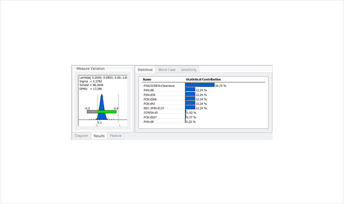
- Analyzes distribution and sensitivity
- Biasing for pin/hole joints
- Analysis of worst case scenarios and statistics
- Sizes of references and notes
- Uses placeholder components to simulate the dimensions of non-CAD models
- Automatically supplements the clearance of models
- Distribution and sensitivity charts
- Automatically creates the HTML reports
- Displays nonconformance cases and statistical distribution
- Average and standard deviation
- Displays dynamic results within the tolerance analysis pitchers
- Able to save sigma, DPMU (defects per million units), yield (%), and other results as the parameters of tolerance analysis pitchers
2Benefits
- Assesses the impact of tolerance on the possibility of design manufacture
- Simultaneous engineering for designs that satisfy the manufacture requirements
- Guarantees the design quality through the Six Sigma design method
- Simplifies the design process, improves productivity, and shortens the product release period
MCAD – Creo Flow Analysis Extension
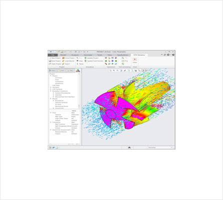
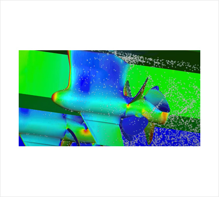
1Features & Specifications
- Calculates internal/external flow
- Displays the results of real-time flow with an animation
- Simulates parallel layout
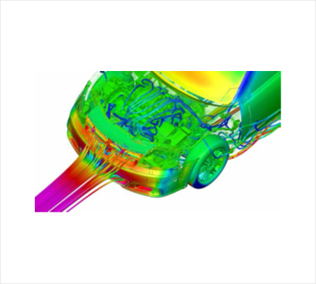
- Simulates the flow and heat transfer
- Scattered flow
- Particles – Simulates each particle according to the flow
- Radiation – Heat transfer due to electromagnetic waves
- Type – Simulates mixture of liquids with similar density
- Transfer/sliding mesh – Simulates the mobility of each substance in the analysis of flow
- Cavitation – Simulates the compression of steam, free gas, and liquid (foam)
- Multiphase flow – Used to simulate both gas and liquid together
- Multicomponent – Other mixtures used for various gases and densities
- Kinetics – Simulates the interaction between fluids and solids
