

MCAD/Mathcad
DIGITEK is always doing our best to think ahead for customers
and create new value for your business.
MCAD – Creo Direct
The fast, easy to use, and flexible 3D direct modeling
PTC Creo Direct must be used as an essential 3D direct CAD solution because it offers the features that you must have. It is easy to use, fast, and flexible so more people can participate in the product development process.
In addition to designing the products that satisfy the fast-paced customer needs, the product development team is constantly pressured to develop dominating products within a short period of time for less. PTC Creo Direct allows the user to use the direct modeling feature throughout the product development process to create and edit the 3D CAD data. In the early stage of conceptualizing the design, receiving feedback from customers or partners, or simplifying the product figures for CAE analysis, PTC Creo Direct provides the right tools to complete the process most efficiently and effectively.
1Features & Specifications
- 3D Solid Modeling
- Integrated 2D Sketch
- 3D Model Editing
- 3D Surface Modeling
- 3D Assembly Modeling
- Interactivity
2Benefits
- Easy to use and learn. The intuitive direct modeling feature allows new or occasional users to identify the features fast to create and edit 3D design
- Faster and more flexible part and assembly modeling enhances the efficiency and productivity of individual engineers
- Uses fast and easy ways to make quick changes to the engineering designs even in the later parts of the process
- Easily integrates and edits the data of other CAD systems for more efficient operation in the multi-CAD environment
- Enhances the efficiency of process
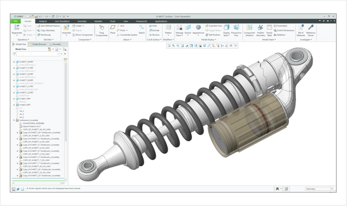
MCAD – Creo Flexible Modeling Extension
An ideal solution for the engineers seeking the highest level of flexibility for any model
TC Creo FMX is an ideal solution for the engineers seeking the highest level of flexibility to modify any model along with all features of the Parametric 3D CAD solution. It offers powerful editing tools that are easy to use and fast, so the engineers can modify the designs without altering their intentions. Engineers using PTC Creo FMX edit the 3D CAD data using the fast and easy direct modeling and maintain their original intentions.
1Features & Specifications
- Fast selection of intelligent figures
- Editing 3D CAD models
- Precise control
- Recognition of figures
- Spreading
- Smooth interaction with PTC Creo Parametric
2Benefits
- Using the intuitive and direct interaction with figures, it can easily and quickly edit 3D designs created with any 3D CAD models
- As the original intentions are preserved and the edited contents are captured with Pitcher, they can be edited later
- The changes that occur in the later part of the process can easily be edited for the engineering designs more quickly without any frustration
- The data of other CAD systems can easily be integrated and edited for more efficient work in the multi-CAD environment
Plastic Part Design - Creo® NC and Tool Facility Solutions
The tools to realize the value of advanced global manufacture environment
More companies are using the engineering teams and manufacture facilities scattered throughout the world to stay ahead of competition in product development. Under these circumstances, it is important to make a smooth transition from product engineering to manufacture process in order to demonstrate exceptional manufacture capacity and successful product development. There are many opportunities for manufacturers, either small or large in scale. They can take advantage of these opportunities with the tools and technologies currently required for top-class manufacturers.
PTC Creo CAM Solutions
- PTC Creo Prismatic and Multi-Surface Milling Extension
- PTC Creo Production Machining Extension
- PTC Creo Complete Machining Extension
- PTC Creo Tool Design
- PTC Creo Expert Moldbase Extension
- PTC Creo Progressive Die Extension
- PTC Creo NC Sheetmetal Extension
- PTC Creo Computer-Aided Verification Extension
- Creo Mold Analysis Extension
Plastic Part Design - Creo® NC and Tool Facility Solutions
Astonishingly fast speed from engineering to manufacture
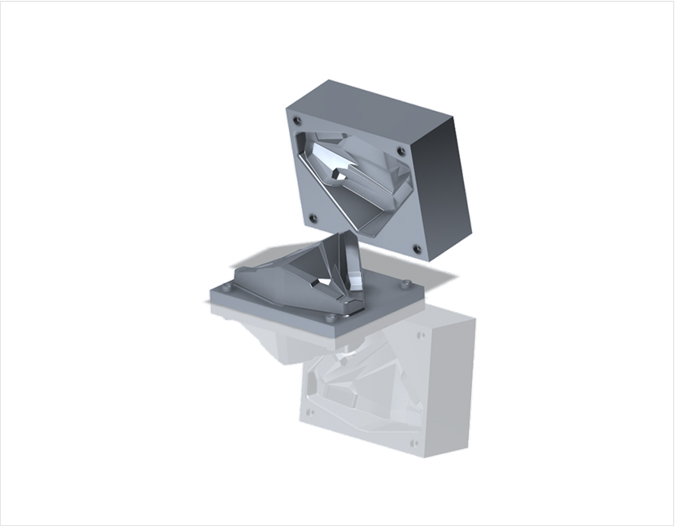
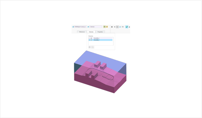
PTC Creo Tool Design Extension (TDX) is an essential 3D CAD tool for professional engineers who are required to insert more quality molds and make casting cavities and patterns fast. Engineers can use PTC Creo TDX’s powerful parametric surfacing feature to make any complicated parting surfaces very easily. PTC Creo TDX automates the complicated processes that consume much time to allow the engineers to invest more time in making quality, innovative tools instead of the redundant design tasks.
It provides various 3D CAD tools specially devised to accelerate the mold and casting engineering work. Engineers use the powerful features of these tools and two easy-to-use GUI (GUI for molds and GUI for casting) to insert any complicated figures and develop casting cavities and patterns fast.
1Features & Specifications
- Multilateral cavity layout, including singles, rectangles, rounds, and variables
- Creation of draft marks for thin walls and instant analysis
- Simulation of mold opening sequence including verification of interference
- Creates detailed drawing of production quality, including BOM (Bill of Material) and balloon memos
- Instant production of runners, gates, and sprues and automatic creation of parting services
- Model contraction is compensated by assigning the dimensions of the entire model with X, Y, and Z or adjusting the rate of magnification
- Guarantee of optimum quality – As mold insertion is produced in reference to the engineering parts figures, the latest engineering parts are always applied to the cavity
- Insertion solid models are produced to maintain links to the PTC Creo NC products:
- Molds are automatically inserted and NC tool routes are updated when engineering parts are changed
- Removed the needs to make conversions between parts engineering, mold engineering, and NC through perfect compatibility with other applied programs of PT Creo
2Benefits
- Mold gradient, undercuts, thicknesses, and projection areas are evaluated by graphic and immediately modified
- Engineered within two GUI (mold and casting) that guides to the mold, casting cavity, and pattern-creating processes
- All pitchers, including gradient, round, complicated surfaces, and parting lines are created and edited to improve moldability
- Isotropic and anisotropic contraction can be corrected
- Patterns and sand cores can be built in reference to the engineered parts
- Automated features
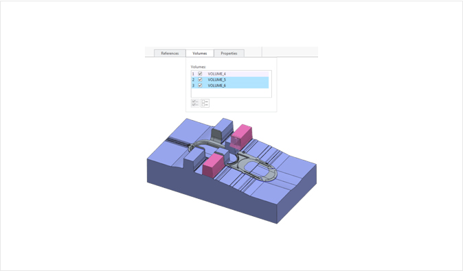
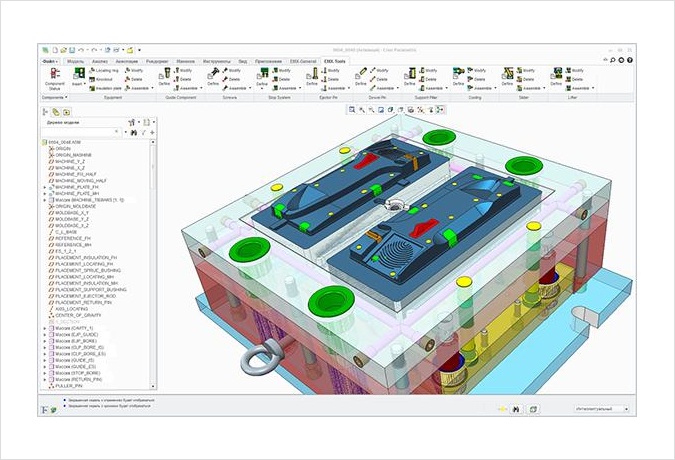
MCAD – Creo Expert Moldbase Extension
Improves the speed and accuracy of moldbase engineering and detailing
The biggest challenge manufacture engineers are confronting today is to improve the quality and speed of moldbase design and detailing and secure time to enhance innovation. Therefore, the most successful mold producers in the world choose PTC Creo Expert Moldbase Extension (EMX). PTC Creo EMX is an essential tool mold manufacturers and tool manufacturers must add and eliminates any time-consuming repetitive tasks and the needs of data conversion that usually delay the product development process.
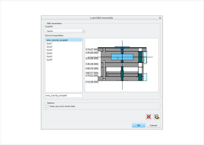
With PTC Creo EMX, engineers can create a moldbase layout in the 2D environment they are accustomed to using to convert it into a 3D model automatically to take advantage of 3D engineering. The 2D GUI optimizes the design and the figures can be updated automatically in the moldbase development process. Also, users can choose from the catalog of standard components (DME, HASCO, FUTABA, PROGRESSIVE, STARK, etc.) or user-defined components. The 3D models resulting from the process are used to check the interference while opening the mold and to create the detailed production drawings and BOM automatically.
1Features & Specifications
- Automated assembly of specialized 2D GUI components that can immediately define the moldbase and components – Easy-to-use ‘pick & place’ feature
2Benefits
- Realizes instant ROI based on significant improvement of productivity
- Preserves the internal mold design technology and captures the standard and exemplary cases of designs created by the company in the mold assembly and components
- Simultaneous engineering of design parts and manufacture parts
- Removes data conversion with the basic PTC Creo 3D CAD solution that is completely compatible
- The corrections are automatically updated, so the changes that occur in the later part of the engineering cycle are easily integrated
- Saves the cost of scrapping and rework by simulating interference and using standard components
- Uses intuitively used tutorials and documents to shorten the training time
- Automated assembly of components – Easy ‘pick & place’ feature
- All required clearance holes, threads, and counter bores automatically added to metal sheets
- The level of parts level pitcher is already assigned
- User-defined components can be created, saved, and reused
- Automated layering and simplification for easy view
- Displays standard and non-standard mold components
- Possible to accept customer parts in any step of the entire process
- Inclusions in the supplier catalog: DME, DMS, EOC, FUTABA (Misumi), HASCO, KLA, MEUSBURGER, PEDROTTI, RABOURDIN, STRACK, PROGRESSIVE, NATIONAL, PCS, LKM, etc
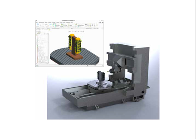
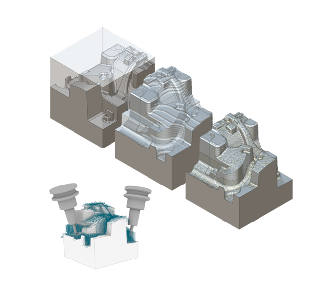
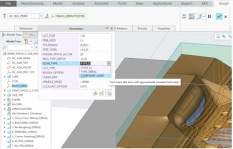
MCAD – Creo Mold Machining Extension
For special processing needs
We introduce Creo Mold Machining Extension to help those engaging in one-time or small-batch engineering. Objects such as molds, tools, electrodes, and Daiwa are often needed to be produced once. Therefore, it is sometimes more practical for product developers to create a fast tool route rather than a process used to produce hundreds or thousands of products. Creo Mold Machining (MMX) offers specialized 3-axis and numeric control processing features on the Creo platform. The NC tool route is also updated when a design or tool is updated. Creo MMX is operated based on ModuleWorks and optimized for molds, dies, electrodes, and prototypes. Creo MMX has many benefits in terms of efficiency, quality, cost-saving, and customer satisfaction.
1Features & Specifications
- 3-axis milling
- 4/5-axis positioning milling
- Hole boring
- Library of tools and supports
- GPOST: Creation of NC Post-Processor
- NC simulation based on Moduleworks
2Benefits
- Improves product quality and consistency of manufacture by creating direct tool routes for solid models
- No need to convert data as a part of integrated CAD/CAM solution
- Updates engineering change and related tool routes to save market release time
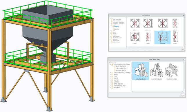
MCAD – Creo Advanced Framework Extension
Enormous speed from engineering to manufacture
Provides simple yet powerful features for designing certain frameworks for engineers and designers to build structural framework much faster.
PTC Creo AFX offers ways for engineers and designers to significantly improve the accuracy and productivity of structural framework assembly and definition. This module is default for PTC Creo products, so it can share intelligent 3D models fast and easily in all steps of the project including designing, detailing, analysis, manufacture, and final assembly. Now, structural framework can be defined more swiftly even if the schedule is tight.
1Features & Specifications
- Top-down design process
- Structures using standard aluminum pushing
- Structures using user-defined beams
- Designs connection between beams
- Creates automated BOM including stock tables
- Creates welding regardless of assembly structures
- Automatically creates engineering drawings
2Benefits
- Uniform integrated design platform
- Simple, convenient, and productive
- Powerful performance
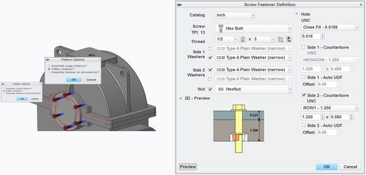
MCAD – Creo Intelligent Fastener Extension (IFX)
Improves productivity of design through user-defined fastener library and automated verification
PTC Creo Intelligent Fastener Extension (IFX) expands the hardware fastener feature of PTC Creo Parametric™. PTC Creo IFX has added the features to user-define hardware library, enhance flexibility of arrangement, and provide exclusive verification tools to users
Assembly of fasteners such as screws, bolts, nuts, washers, and dowels require a great deal of handiwork. Therefore, users should be able to identify the diameters of holes that are paired with each part accurately for hardware assembly. PTC Creo Parametric can automate this process, in addition to the access to the inclusive catalog (ANSI, DIN, JIS), to save the time required to arrange and assemble fasteners by up to 90%.
PTC IFX is based on these features. PTC Creo IFX enhances the productivity of users and prevents errors and spreading parts with various features, including perfectly user-defined library, fastener assembly without creating assembly reference, various arrangement options, and various design verification tools.
1Features & Specifications
- Expanded library including dowels
- User-defined libraries
- Supports fastener directions
- Assembles fasteners using references pattered in a single workflow
- Arranges several partners at once without creating external references
- Automated verification
2Benefits
- Improves productivity by automating redundant processes
- Relieves fast increase in the number of parts
- Standardizes customer work
- Improves design workflow
- Improves accuracy of design
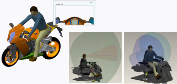
MCAD – Creo Human Factors Analysis Extension
Simulation of interactivity between products and people using digital modeling of human futures
In the market of fierce competition today, it is becoming essential to introduce ‘man-centered’ approaches to design and engineering. Designers and engineers in aerospace and defense, automotives, industrial equipment, electronics and high-tech industries must comprehend and optimize the process to manufacture, use, and maintain/manage products to secure market competition to satisfy customer needs and manufacture products that are easy to use.
Creo Manikin Extension is an ideal solution that can visualize, simulate, optimize, and exchange the interactivity between people and products in the early process of design to save time and cost of product development.
Digital modeling of human figures allows the designers to add 3D digital human figures to 3D CAD product models to create designs for the people. The digital human figures, also known as mannequins, are advanced 3D mechanisms that express the features of human body, including the build, shape, vision, mobility, power, and comfort. As digital human figures can be customized to match the desired gender and race and manipulated in real-time, designers can better understand how the products interact with those who handle them, such as consumers, operators, installers, assemblers, and maintenance workers, and the products.
- The library of human figures that can capture and reuse the data of human figures
- Includes collision distance, clearance, mass, etc
- Creates a window to ‘check’ how the human figures would use the window
- The vision cone is used for the designer to identify the objects within the various ranges of vision
- Identifies the reach of human figures based on the range of reach
- Visualizes the vision according to the movement of the head and the eyes
- Uses the movement of human figures to consider comfort, clearance, allowance, and other design considerations
1Features & Specifications
- Uses the tool set exclusive for human figures to quickly add a human figure to Creo and customize it according to the variables defining its gender, nationality, build, etc
- Evaluates and maximizes product potentials in the world market by measuring the build of a wide pool of human figures
- The structure of digital human figures aligns with ISO/IEC 19774, the H-ANIM standards
2Benefits
- Reduces time, budget, and aging related to the physical prototype
- Complies with the safety, health, ergonomic, and workplace standards and guidelines
- Optimizes products aligned with the identified objectives of the global market
- Uses visual simulation solutions for powerful and clear communication to exchange and share the complicated interactivity between people and products
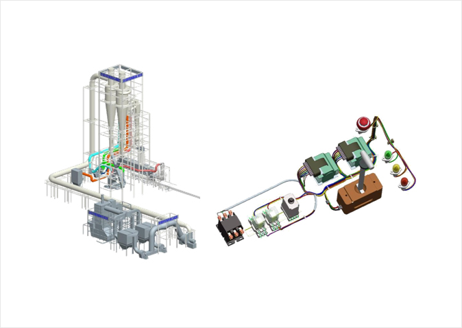
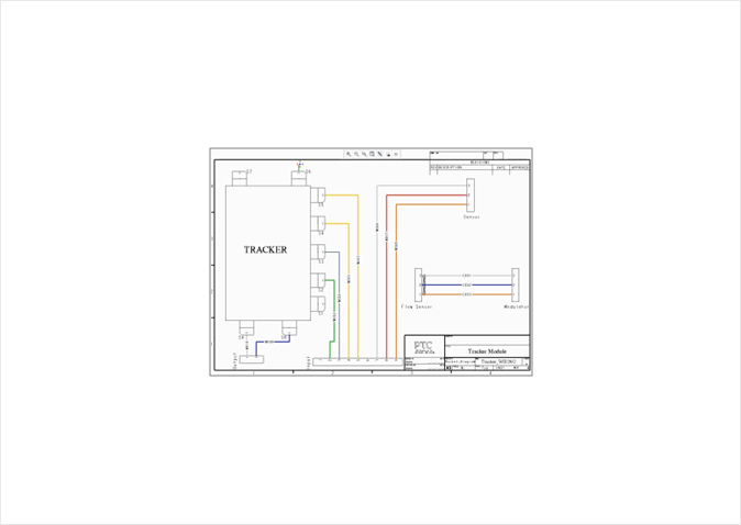
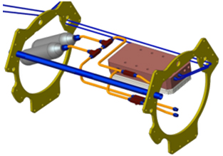
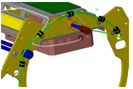
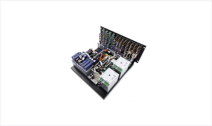
MCAD – Creo Piping and Cabling Extension
Fast processing of piping and cabling design process
PTC Creo Piping and Cabling Extension (PCX) is the perfect 3D solution that supports all kinds of industries and all types of piping and cabling to simplify and accelerate the entire design process. With PTC Creo PCX, even the most complicated processes can be executed easily, including products containing complicated cable and harness mesh, pneumatic or hydraulic hoses, high-pressure and low-pressure tubes, copper work, and pipes with big bores.
Piping Design
- Accurate and efficient pipeline and fitting routes.
- Comprehensive tool set to insert fittings.
- Strengthens the pre-defined rules by detecting violations.
- Completely controls the direction of flow.
- Piping route is verified to prevent errors.
- Information is easily extracted from designs for printing.
Cabling Design
- Improves the reality of bundle display and the downstream use of cable design information.
- Electronically documents the entire design process.
- Automatically creates the completely defined 3D harness.
- Sets the harness routes for multiple users at the same time for automation of 3D harness flattening.
- Improves the efficiency of communication.
1Features & Specifications
- Piping diagram
- Cabling diagram
- Design reuse
- 3D CAD
- Improves bundle display
- Realistically depicts shrink-wrap pipes through bundle conversion
2Benefits
- Captures and documents structure information and manufacture documents
- Automatically captures all related system information, such as structural designs, virtual prototypes, and manufacture documents to minimize errors and reduce time-consuming processes
- Completely automates routes to quickly decide the optimum routes for manufacture, cost, and service
- Guarantees application of design rules and structural logic rules based on specifications
- Reuses the standard symbols, connectors, and fittings included in the user-defined library to improve the design speed
- Verifies virtual interference and feasibility of automated manufacture to save cost and design time with no physical prototypes needed
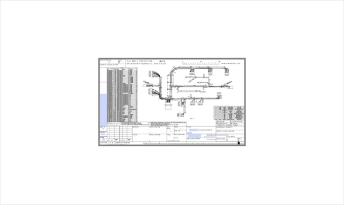
MCAD – Creo® Harness Manufacturing Extension
Automated creation of manufacture documents
PTC Creo Harness Manufacturing Extension (HMX) significantly reduces the manufacture document creation time from several hours to several minutes to accelerate product release.
PTC Creo HMX significantly reduces the time required to create the standardized manuals and technical resources for professional users. The document can be created with the click of a button anytime in the design process, so designers can secure more time for design optimization and work more flexibly with manufacture partners.
1Features & Specifications
- Number of electric parts supported (connectors, devices, splices)
- Supports overbreak
- Supports cosmetic pitchers: Tape, tie wrap, marker, and thermal contraction
- Circulating topology and quarterly bundle pitcher
- User-defining drawing templates
- Supports various drawing sheets that expands harness drawings horizontally
- Mapping of user-defined parameters of spool part number
- Automatically numbers the pages of BOM and wire list on the standard drawing sheets
- Automatically arranges 3D assembly view and automatically creates parts view
2Benefits
- Uses an intuitive user interface to easily create documents in accordance with the pre-defined standards
- Easy to apply the changes made in the later part of design through an optimized documentation process
- Standardizes the documentation process
- Optimizes the manufacture cost
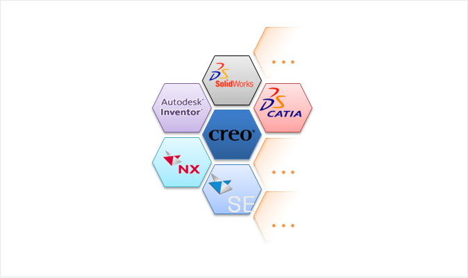
MCAD – Creo Unite Technology
An innovative way to resolve the issues in the multi-CAD environment
PTC Creo® with the Unite Technology offers users innovative features to improve productivity in the multi-CAD environment. Users can effectively cooperate to integrate the CAD system throughout the system platform for the engineering team to improve product quality, feasibility, and timely shipping for the next level of efficiency.
In today’s multi-CAD environment, it can be a big challenge to use the various CAD systems for effective operation. The Unite Technology resolves these issues by allowing users to import and open non-PTC Creo files and save them as non-PTC Creo formats to create and manage their designs for any CAD platform.
1Features & Specifications
- Import
- Open
- Update
- Save as
2Benefits
- Easy reuse of existing data
- Data conversion as needed
- Reduces the number of CAD platforms and the cost of software licensing, support, and training
- Improves engineering productivity and IT efficiency
- Realizes higher level of simultaneous engineering
- Promotes data reuse and sharing
- Creates neutral formats and reduces the needs to manage them
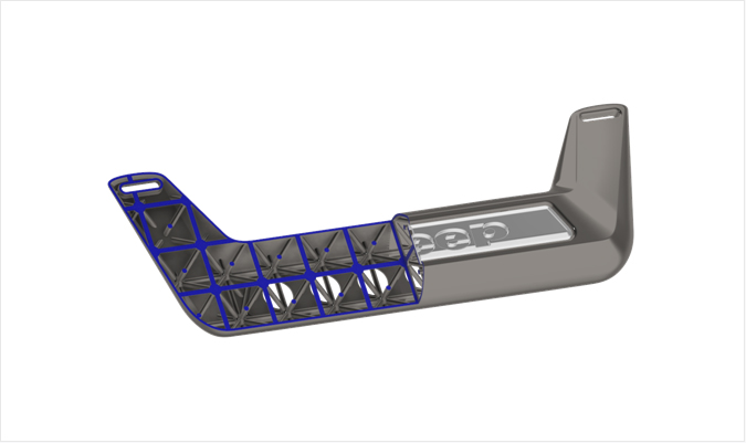
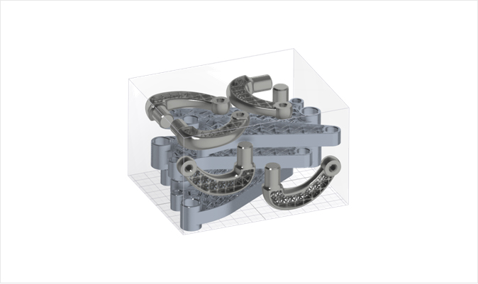
MCAD – Creo Additive Manufacturing Extension
The technology to print what you see as-is
Additive manufacturing (3D printing) is the process of piling thin layers of materials one layer at a time to build an object. The definition is simple, but the actual 3D printing process is not so simple. Designers usually have to use various software packages to export, redesign, and optimize each model and import it back into the program.
Now, they can design models, optimize and verify models, and check printing all in one design platform. They can print what they see as-is. The highly complicated figures that can only be created through additive manufacture with Creo 4.0 can be created, optimized, and verified.
1Benefits
- All in one environment
- Creates a grid
- Supports connection to printer
- Creates and manages printer tray
