

MCAD/Mathcad
DIGITEK is always doing our best to think ahead for customers
and create new value for your business.
MCAD – Creo Parametric
Where innovative products are born
Creo Parametric provides access to a more extensive and efficient product designing environment based on PTC global resources and success secrets accumulated for decades.
Using Creo Parametric and the expanded modules, it supports 2D CAD, 3D CAD, Parametric and direct modeling, so it can create, analyze, confirm, and share the design downstream. Actively try out the innovative features related to additive manufacturing, model-based definition, and smart connected design. Also, reuse the existing CAD data to easily build an AR platform.
Creo Parametric with the most powerful 3D product design tool set and the new product design features for the future will help you reach your fullest productivity. Design smarter for today and for the future.
1Features
- 3D solid modeling
- Powerful assembly modeling
- Detailed documents including 2D and 3D drawings
- Technical surface work
- Freestyle surface work
- Sheet metal modeling
- Welding modeling and structural framework design
- Analyzing features
- Graphic features and integrated design animation
- Design for additive manufacturing
- Data exchange
- Data work other than imported Creo
- Integrated NC features
- Perfect library including parts, pitchers, and tools
- Render Studio
2Benefits
- More efficient and flexible 3D design details to enhance productivity
- Creates 3D models for parts or assembly fast and easily
- Exclusive tool sets for large-sized assembly work
- Inclusive surfacing to improve the aesthetic elements of design
- Instant access to the parts library containing screws, bolts, nuts, and washers
- Generative Design: Optimize development of product design using A.I. during the design process
- Comprehensive Additive Manufacturing : Improved probabilistic lattice support and able to identify and track footnote type edge
- Multi Body Modeling : Effective implementation of separated, bordered, overlapping geometry
- Support GD&T Advisor for assembly
- Inseparable Assemblies for parts purchase – Creates a single file for multi-component assembly
- Design Item group that shows body and quilt listed at the top of model tree
3D Solid Modeling
- Produces precise figures regardless of the complexity of model
- Sketches the dimensions automatically for fast and convenient reuse
- Quickly produces powerful engineering features such as rounding, chamfering, and holes
- Produces part derivatives using family tables
- Parts level BOM using Multibody
- Model with multi material
- Creates multiple holes on one feature based on sketch location
- Supports lightweight for all types of holes
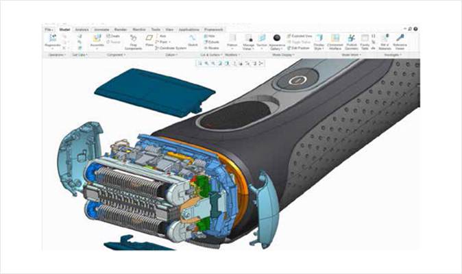
Powerful Assembly Modeling
- Provides more intelligent and faster assembly modeling function
- ‘Improvised’ simplification of expression
- Uses the unique Shrinkwrap™ tool for accurate modeling in small sizes
- Detect collisions in real-time
- Easy to manage parts components for purchase using inseparable assemblies
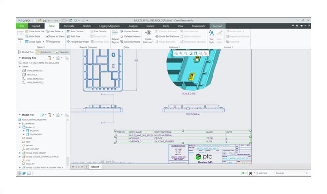
Detailed Documentation Including 2D and 3D Drawings
- Produces 2D and 3D drawings in accordance with the international standards such as ASME, ISO, and JIS
- Automatically creates related BOM and notes in balloons
- Automatically creates drawings using templates
- Supports nonlinear cross hatching pattern using industry’s standard pattern file format(*.pat)
Technical Surface Work
- Develops complicated surface figures using various special features, such as Sweep, Blend, Expand, and Offset
- Trims and expands surface using tools, such as Push, Rotate, Blend, and Sweep
- Executes surface processes, such as Copy, Merge, Expand, and Modify
- Defines complicated surface figures
FREESTYLE Surface Work
- Uses modeling features with hierarchy to quickly create freestyle figures and surfaces
- Immediately reuses quality surfaces with parameters in the detailed 3D design process
- Multilevel modeling strengthens surface control to add details without altering the existing shape
- Tangent control aligns the figure to the existing curve or edge for parametric control of freestyle figures
Sheet Metal Modeling
- Uses simplified user interface to create walls, bends, punches, notches, shapes, and reliefs
- Automatically creates flat patterns based on 3D figures
- Calculates various bends to create the flat pattern of design
- Creates several flat wall on one feature
- Creates multiple holes on one feature based on sketch location
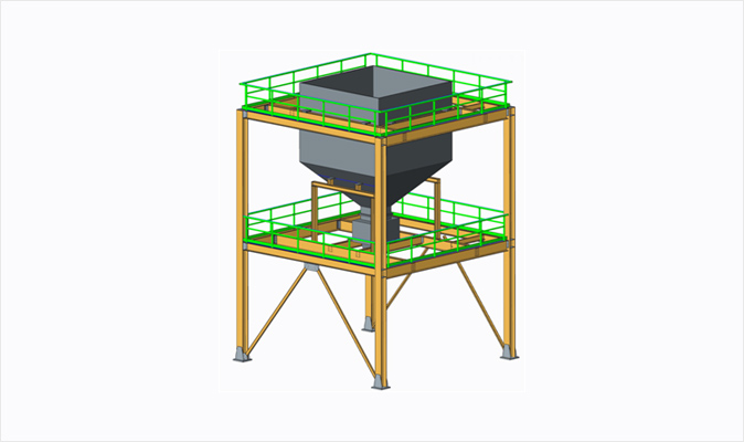
Welding Modeling and Structural Framework Design
- Optimum user interface for the structural framework design process
- Defines the combined requirements
- Extracts meaningful information from the model, such as mass properties, clearance, interference, and cost data
- Easily writes complete 2D welding documents
- Automatically creates intelligent component library and downstream outcomes to accelerate the speed of frame design compared to the standard method
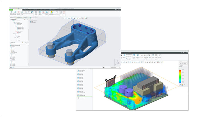
Analysis
- Fundamental analysis of static structures for parts and assembly
- Verifies the kinetic motion of design
- Through the interactivity of Mathcad®, the engineering calculation software, integrates the Mathcad worksheets with design to predict the motion and derives the major parameters and dimensions (selective use of Mathcad)
- Adds Microsoft® Excel® to the design
- Integrated analysis and calculation of measurements including evaluation of gradient and 3D thickness
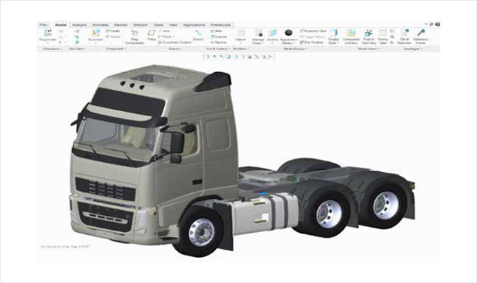
Graphic Features and Integrated Design Animation
- Reflection feature added for gradation to express various materials, including metal, glass, paint, and plastic. These pattern styles are expressed in a way that they realistically interact on a model while supporting dynamic transitions
- Accurate and realistic product images are quickly created and large-sized assemblies are smoothly rendered
- Maintains the effect of shadows, reflections, textures, and transparency while dynamically modifying the figures
- Creates assembly/disassembly animations in the modeling environment
- Uses the options including the mechanism simulation to easily reuse models
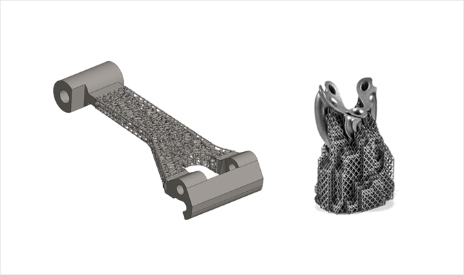
Design for Additive Manufacturing
- Defines the settings for several 3D printers
- Assigns the clipped view of 3D models and provided materials to the printer tray to adjust and display magnification
- Quickly reviews feasibility for 3D printing and easily corrects identified issues
- Uses the Stratasys Connex printer to print the parts and assembly directly on Creo and defines surface finishes, materials, and colors to calculate the build and materials
